Bosch-style connector
A sealed automotive-style sensor or field-device termination. Terminal geometry, pinout and equipment profile must match the specific device.
Keddeh / BRAINK · Six-port compute architecture
Six bilateral CAT6 ports. Upgradeable compute. A rugged node bringing power, data and local intelligence into one equipment-level architecture.
The later KEDDEH / BRAINK platform study. Engineering development and integration enquiries.
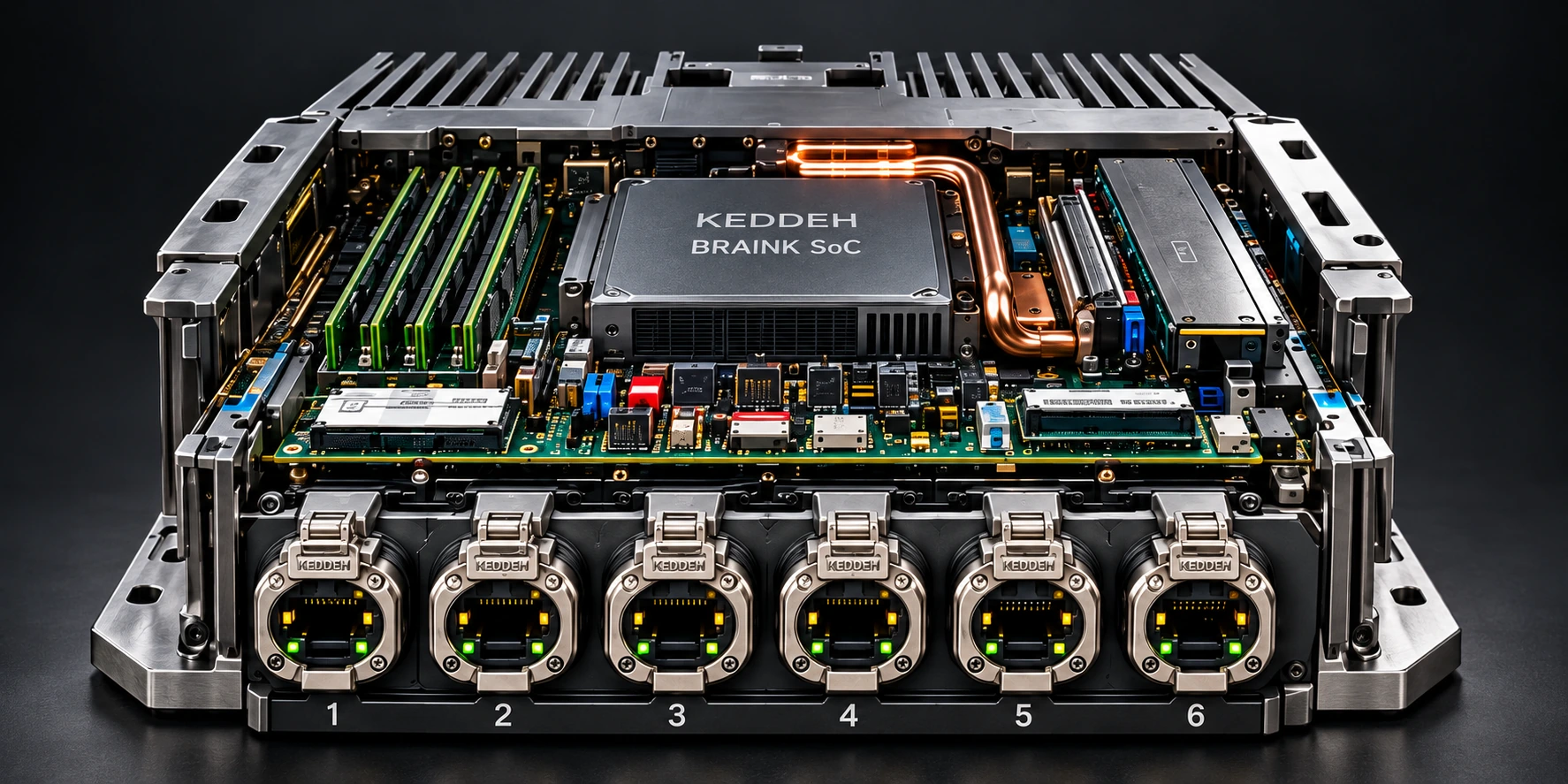
CENTRAL R1, 5 October 2026. Presentation refinement of the original blueprint’s product render. Six CAT6 port openings and the source physical architecture are retained. This is design imagery, not a physical prototype photograph; ratings and qualification remain unverified.
01 / Enclosure
The CENTRAL R1 render places the compute board and six-port face in one metal chassis. Rear heat-dissipating fins, mounting ears and service access are visible in the source design. Thermal and environmental performance remain qualification work.
02 / Compute
The central CPU/GPU SoC is the compute heart of the CENTRAL R1 study. A real-time MCU and per-port control functions have distinct jobs beside it: equipment control, circuit testing and observed response remain tied to qualified interfaces.
03 / Expansion
The source blueprint locates ECC memory beside the central processor, with PCIe expansion and NVMe storage. It proposes serviceable RAM, accelerator and I/O modules. Capacity, component compatibility and hot-swap behaviour are design targets to qualify.
04 / Six ports
The later CENTRAL R1 design gives every front port power-in / power-out, data and control responsibilities, with discovery, current limits and fault isolation. The earlier circular multipin controller is preserved in the source history, not treated as a compatible connector revision.
01 / The platform direction
The later design brings compute, storage and six identical bilateral CAT6 ports into a serviceable central node.
Follow the source drawing from the CPU/GPU and memory through per-port control to the power plane. Each port is designed around power, data and control, with its own observed state.
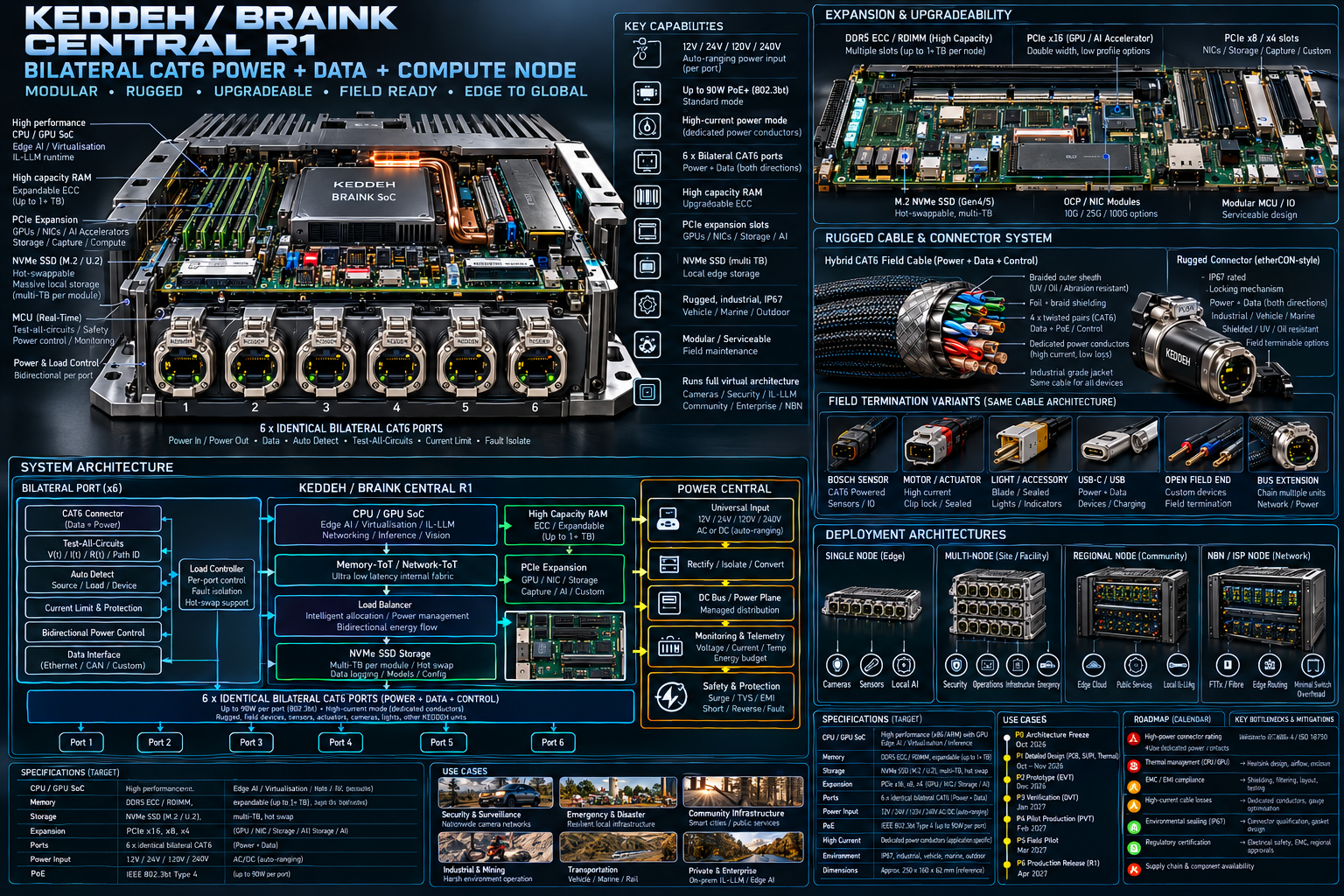
The blueprint’s IP67, up-to-90 W PoE, 12 / 24 / 120 / 240 V input and high-capacity memory labels are design targets, not tested ratings or certifications. Mains voltage is not permission to use a generic CAT6/RJ45 cable or connector for mains. Its October 2026–April 2027 roadmap is a historical planning target, not a current launch or shipping commitment.
02 / The connection to the field
A braided field cable, a rugged bus connector and device-specific terminations. The original cable study follows the connection all the way to the equipment.
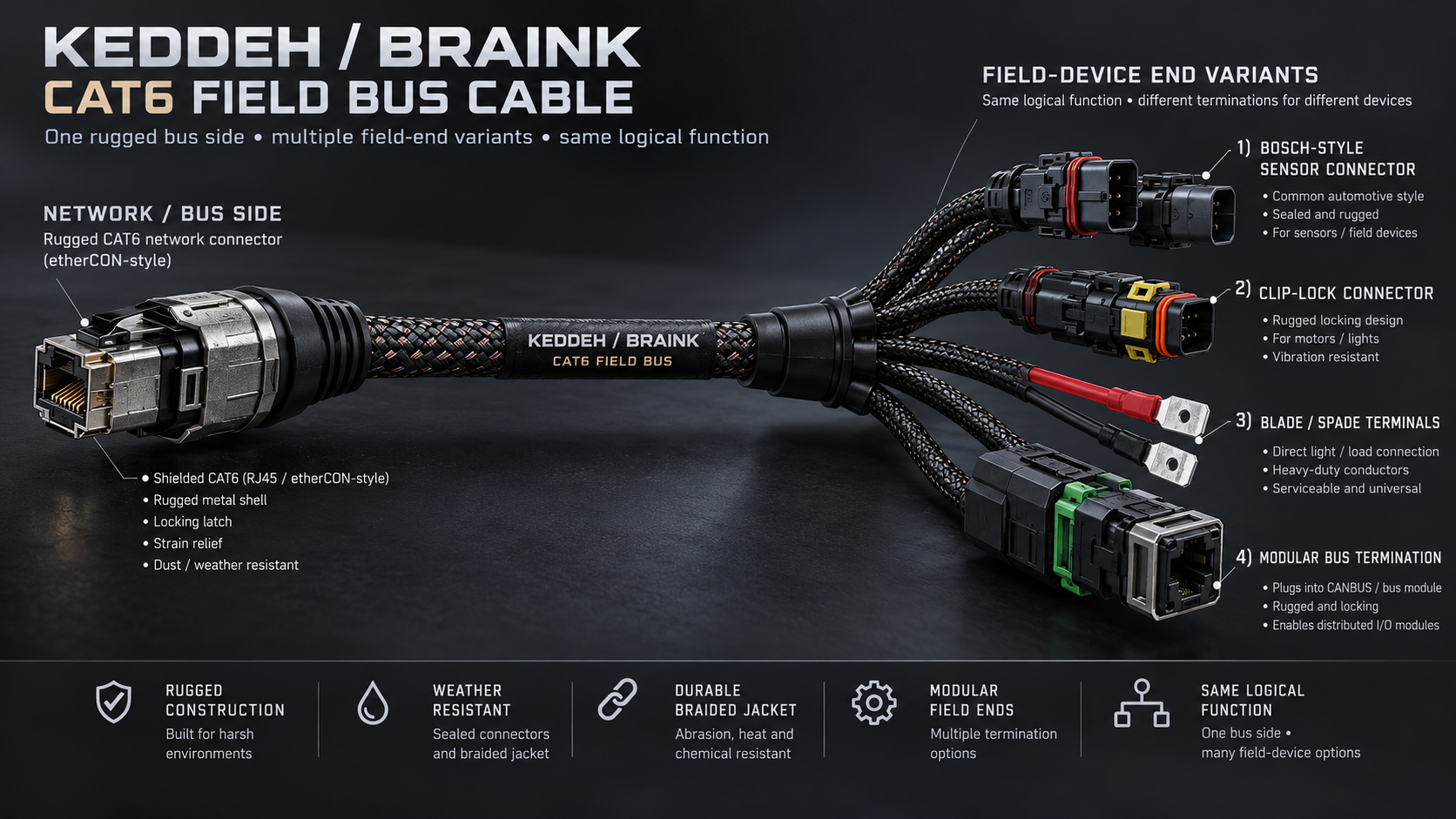
A sealed automotive-style sensor or field-device termination. Terminal geometry, pinout and equipment profile must match the specific device.
A locking field end for compatible motors and lights. Vibration retention and the load’s current, switching and protection needs define the build.
A direct field-termination option shown for lights and loads. The actual terminal, conductor and isolation ratings must be selected for the installation.
A rugged bus end for distributed I/O and sibling modules. The supported electrical and signalling interface must be specified at both ends.
A cable and connector format does not declare the power rating, pin assignment or protocol. The later hybrid cable drawing adds dedicated power conductors.
A CAN application needs the matching transceiver, physical layer, wiring and termination. CAT6-shaped connections do not automatically provide Ethernet or CAN compatibility.
KEX-CAN logical records identify and relate state. They do not replace an electrical interface, a device driver or a qualified power path.
The proposed common-contact platform and interchangeable keyed housings remain a connector-system development direction. OEM contacts are not assumed interchangeable. A passive adapter cannot establish electrical, sealing or device compatibility.
03 / The equipment around it
Choose the equipment you want to connect. Read the complete input-to-result path here, then use that application to prepare an integration enquiry.
Connect the physical bay to the people doing the job. The proposed environment brings website and server services, user and file spaces, mechanic workstations, advisor desktops and repair modules into one coordinated workflow.
A repair job, verified vehicle and bay identity, plus a time-stamped hoist-state observation.
A qualified sensing adapter reports the equipment state. The workstation receives job context through a scoped service interface.
The guide explains repair material. A separate file agent handles authorised files; equipment motion remains with its qualified controller and safety controls.
Return the source, observation time, job identity and actual result to the mechanic and permitted advisor view. Missing or stale state remains unresolved.
Physical interfaces and scoped software roles
Compatible sensing and equipment interface
Scoped files, repair context and advisor view
Equipment knowledge within permitted interfaces
Explanatory system schematic. No connected hardware or live telemetry.
01 / Power
Hardware modules provide the proposed interface to compatible bay equipment. A hoist’s reported state can inform the job context only through an engineered sensing interface; motion control remains a separate qualified responsibility.
Workshop outcome: establish which vehicle and job belong to a bay, alongside sourced equipment state.
02 / Control
Relate the bay’s reported state to the repair job, the mechanic’s workstation files and an authorised advisor or office view. ServerSpace supplies a source-backed execution and coordination service to evaluate for this integration.
Workshop outcome: define a shared job context and permitted views rather than copying disconnected status updates.
03 / Local intelligence
The local-first guide supports the mechanic with repair context. It has no intrinsic equipment-control or file-deletion capability. File agents and equipment agents are distinct bounded “realities”, each with independent state and permitted interfaces; the guide cannot invoke an operation absent from its interface. Scoped handoffs connect these roles. Drift mitigation keeps learning and adaptation within the role: it cannot silently add tools, expand authority or change identity. Scope changes require an authorised transition.
Workshop outcome: useful guidance and scoped handoffs without giving one assistant every capability. This is the intended separation by construction, not a claim that whole-estate isolation has been formally proven.
Illustrative integration workflow, not a deployed workshop or live hoist connection. Bay and hoist state must come from a qualified interface and be associated with a verified vehicle/job identity. Reported state does not authorize hoist motion or bypass safety controls.
Three sibling modules share the bed environment. Each is intended to handle its own work or the whole environment, with control, power interfaces and retained state considered together. Select a peer to explore the same capability from each position.
A particular bed switch requests a defined function; the request identifies the destination and allowed timing.
Any of the three full peers may host the switch or a compatible rated driver. Network ToT relates the request across those interfaces.
The selected function stays within its load envelope, interlocks and fault-response policy. No peer receives broader authority merely by taking over.
Qualified sensing supplies the response and Memory ToT retains it. The one-surviving-peer requirement needs measured fault and recovery tests.
Peer arrangement · no fixed master
Control · power interfaces · retained state
Control · power interfaces · retained state
Control · power interfaces · retained state
Any peer → own functions or the whole bed environment
Explanatory system schematic. No connected hardware or live telemetry.
01 / Module 1
Module 1 is a peer with its own control, connected interfaces and retained observations. A switch may be connected here while the matching load is connected to another module. Its role is assigned by the installation; it is not a permanently dedicated power-only module.
Design intent: each module can handle its own work or the whole bed environment.
02 / Module 2
Module 2 has the same intended controller capability. Network ToT relates a request to its destination and timing across siblings; Memory ToT retains observed response. Distributed placement does not turn this module into a fixed middle stage.
Design intent: keep input, action and measured response related across peers.
03 / Module 3
Module 3 is another full peer. The requirement is for one remaining controller to manage the loads if two peers fail. Power paths, drivers, retained-state recovery and common-cause failures need target-specific engineering and measured fault testing.
Design requirement, not a demonstrated result: any surviving peer must be qualified to take over the defined bed environment.
Each module is intended to handle its own work or the whole bed environment. A remaining controller is designed to manage the loads if two peers fail; this is a requirement, not a completed failover test. Clinical use needs target-specific electrical, mechanical, fault-response and medical-device qualification. No medical certification is claimed.
Distribute switch collection, sensing and compatible load control across sibling modules. Give lighting, coil loads, injectors and small motors their own defined interfaces within the whole-vehicle electrical retrofit design.
A switch-collector supplies the chosen vehicle input, with a defined operating condition and destination.
A compatible driver controls a specified lamp, coil load or small motor. Higher-voltage loads use a separately rated and isolated relay or contactor path.
The installation declares allowed functions, timing, current limits and response to link loss. Connector shape alone establishes none of these.
Compare the requested action with sensed current, position or state, as appropriate, and retain that readback. Unknown or failed responses do not become success.
Physical interfaces and scoped software roles
Qualified lamp, coil-load or motor driver
Distributed input, timing and readback
Equipment meaning and retained operating context
Explanatory system schematic. No connected hardware or live telemetry.
01 / Power
Use battery-managed or internally managed low-voltage power where appropriate. A microprocessor/control role can command an external relay and microcontroller setup for a higher-voltage load.
Integration outcome: a load-by-load electrical profile rather than assumed connector compatibility.
02 / Control
A switch-collector module supplies the input. Network ToT relates it to a compatible lamp, coil-load or motor module, with declared timing and measured response retained in Memory ToT.
Integration outcome: a reviewable input → action → readback relationship across the vehicle.
03 / Local intelligence
An AI-equipped local control environment brings site- and equipment-specific meaning, operating history and defined authority together. Edge software supplies the local-first software approach.
Integration outcome: scope an equipment-aware local expert with explicit operating boundaries.
Installation, driver compatibility, timing, failover and road-use suitability need vehicle-specific engineering and qualification. This design does not establish autonomous-driving capability or automotive certification.
These are design applications, not deployed customer case studies. The next deliverable is a defined integration scope and acceptance plan.
04 / Design, evidence & next steps
These original studies establish a physical direction. An integration turns that direction into a chosen revision, a load profile, a qualified interface and an acceptance plan.
Source provenance: original KEDDEH / BRAINK design renders supplied by Aboudy Keddeh, 5 October 2026. The three linked PNGs are preserved unchanged. The hero is a presentation refinement of the later CENTRAL R1 product render. These images are design renders, not manufactured-product photographs or verified PCB layouts.
Select the module and a documented electrical envelope. Observe only the permitted diagnostic pulse. Assign the input, task, output and timing through Network ToT; retain the response in Memory ToT and reverify on reconnect.
Unknown, ambiguous and faulty paths stay unresolved. A pulse/path signature does not establish universal device recognition. Voltage/current measurements need aligned samples, units and measurable current; reactive transients do not automatically yield calibrated DC resistance.
IL-LLM local-first intelligence carries equipment-specific meaning. BRAINK augmented learning is intended to produce a localised expert using retained observations and permitted operations. Learning can inform a proposed change within defined authority; it does not establish autonomous safety control.
Guide, file and equipment agents have separate state and interfaces. A guide has no intrinsic equipment-control or file-deletion capability. Scope changes require an authorised transition.
The broader module direction includes a single-ingress aluminium enclosure, a slide-in “pce” board, an upgradeable CPU/GPU position and durable “SSDRAM”. MRAM-backed retained state belongs to the multi-failover design. Interface standards, component choices, service procedures and recovery performance need qualification against the selected revision.
A module can serve a power-controller or microprocessor role. Battery-managed low-voltage power and an external relay / microcontroller arrangement for higher-voltage loads need distinct engineering. Keep the low-voltage command path separate from the rated, isolated load path; relay and contactor suitability are load-specific.
Define command timing, watchdogs, interlocks, loss-of-communication response and recovery for each target. Blanket power removal is not safe for every load or bed function. Shared power, connectors and retained-state recovery create common-cause failures that must be analysed.
The hospital-bed three-module requirement includes managing the environment with one remaining peer if two peers fail. This page does not report a completed failover test, a tested prototype or medical / automotive certification.
The intended deployment keeps web-manager workstations web-connected while the local machinery plane has no direct internet interface. Scoped, authorised handoffs relate their work; sharing context does not itself confer equipment control.
KEX addressing, seed, KEX DNA constraints, IL-LLM meaning, vector-based keys and evolving VFS identities have distinct responsibilities. DNA represents constrained state for rehydration and recovery; it is not an executable engine. Address changes are distinct from cryptographic-key rotation. This is the intended architecture, not certified physical air-gapping or proof of whole-estate isolation.
Optional source material for the integration review. The application explanation above is complete without opening these guides.
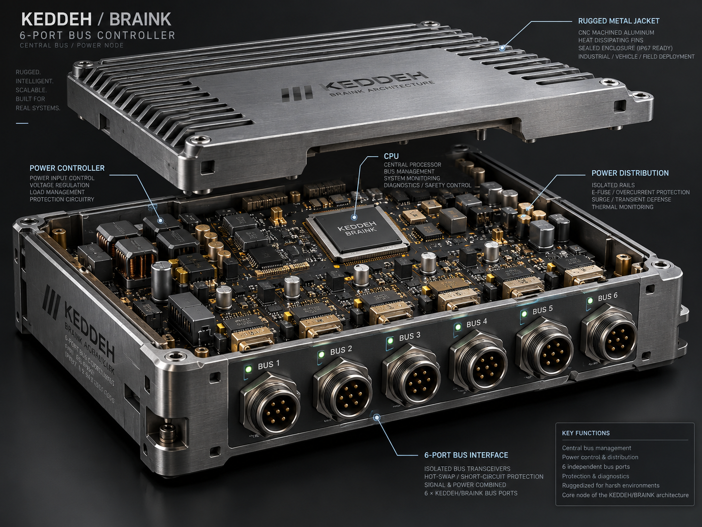
The six-CAT6-port platform drawing, dated 5 October 2026.
The four illustrated equipment-end termination families.
The distinct six-circular-connector design preserved for source history.
Module boundaries, discovery, sibling control and retained observations.
Bay equipment, repair context, workstations and the service advisor.
Read the equipment, metering and acceptance scope for a factory-energy integration.
Read the file, service and access boundaries for an office-network integration.
Your equipment. The next build.
Bring the equipment, environment and intended behaviour. Define the module mix, field terminations, control authority and evidence needed for your integration.
Include the equipment model, input or sensor, intended load or output, permitted operator, and the readback that would demonstrate success. The enquiry opens an editable brief; you review it before sending.
Describe your chosen application or a new equipment interface.
Prepare your hardware integration brief →The design is open for review and integration discussion. Manufactured stock, a shipping date and certified electrical ratings are not offered on this page. No order or payment is placed here.